
Explosion Isolation Design Checklist
How to place and specify isolation devices for ducts, pipes, and interconnected equipment
One minute answer: Explosion isolation is the barrier that stops flame and pressure from traveling through ductwork and piping into connected equipment. This page is the practical checklist, what to protect, where to place isolation, and how to choose between passive and active devices without guessing.
Best for: facilities with dust collectors, silos, dryers, mills, conveyors, bucket elevators, cyclones, or any process line that connects vessels or vents to the building.
At a glance
What you will get:
- A placement checklist for inlet, outlet, return air, and interconnections
- A simple decision path, passive vs active isolation
- Selection notes for common isolation devices, what they are good at, where they fail
- A quote request checklist so your design does not stall
If you only do three things:
- Map every interconnection, including return air, vents, and bypass lines
- Choose the isolation method that matches your process constraints, not the cheapest device
- Verify placement and reset, maintenance access before equipment is installed
Jump to
Why isolation gets missed
What to protect, a simple interconnection map
Placement checklist, where isolation typically belongs
Passive vs active isolation, how to decide
Device guide, what each isolation option is best for
Commissioning and proof, what “done” looks like
Maintenance and reset planning
Quote request checklist
FAQs
Downloads
Why isolation gets missed
Most facilities protect the “main” vessel and forget the connected paths. The explosion does not care about your PFD, it travels down the easiest route, ductwork, pipes, screw conveyors, and pneumatic lines. If interconnections are not blocked, a small event can become a multi-vessel event.
Common blind spots:
- Return air ducts from dust collectors back into the building
- Multiple pickups feeding one collector, and branch lines
- Bypass lines, purge lines, vents, and inspection ports
- Silos or bins connected to collectors, dryers, and packaging lines
- Conveying lines that cross fire areas, walls, or floors
What to protect, a simple interconnection map
Start with one rule, if a line can carry flame or pressure from one location to another, it needs an isolation decision. Draw the map in five minutes, then make the decisions deliberately.
Your interconnection map, minimum fields
- Vessels: dust collector, silo, dryer, mill, cyclone, mixer, filter receiver
- Lines: duct size, length, bends, branch points, direction of normal flow
- Material: dust type, Kst, Pmax, MIE if known, plus any sticky or fibrous behavior
- Process constraints: food grade needs, CIP, sanitation, pressure or vacuum, temperature
- People and building: where the duct enters occupied areas, where it crosses fire separations
Placement checklist, where isolation typically belongs
This is the practical rule set. Final placement should be validated against standards, device data, and your exact geometry, but this checklist catches most misses early.
Placement checklist
- Collector outlet to building or return air: isolation before the duct leaves the collector zone, and before it reaches occupied areas
- Collector inlet branches: isolate high-risk branches, especially long runs, and any lines that connect to multiple rooms or floors
- Between vessels: silo to collector, dryer to cyclone, mill to filter receiver, any vessel pair needs an isolation decision in both directions when applicable
- Conveying lines: isolate at the vessel boundary where flame could propagate to the next location
- Across fire separations: treat wall and floor penetrations as a forcing function, isolate before the penetration when feasible
- Upstream and downstream: verify if you need one-direction or two-direction protection based on where ignition could occur
Passive vs active isolation, how to decide
Passive isolation is attractive because it does not need detectors and a controller, but it is not automatically the right answer. Active isolation adds detection and control, it can be faster, supervised, and more robust across complex layouts.
Decision cheat sheet
| If this is true | Lean toward | Why |
|---|---|---|
| Simple duct runs, stable airflow, clear direction of flow | Passive | Fewer components, lower complexity |
| Multiple interconnections, branch lines, or uncertain ignition locations | Active | Supervised response, can protect in the direction you need |
| You need confirmation, monitoring, and alarms to the plant | Active | Controller-based supervision and event reporting |
| Product contamination is not acceptable | Mechanical active | No suppressant added to the process stream |
| You can accept suppressant in the duct, and want a non-contact barrier | Chemical active | Rapid agent injection can block flame paths in ducts |
Want the high-level flowchart? Download SSI’s decision matrix below, then validate with your specific hazard data.
Device guide, what each isolation option is best for
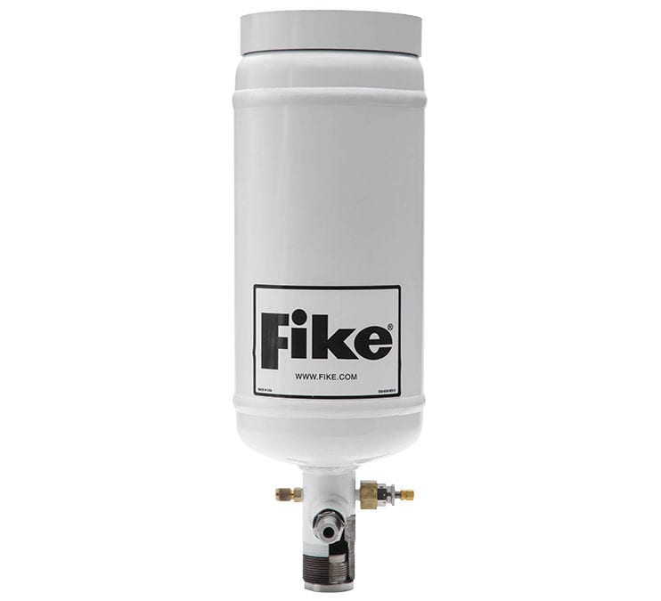
Passive isolation devices
Passive isolation devices typically close from the pressure wave itself, with no external power, and they are commonly used where airflow conditions are stable. The tradeoff is that placement and process conditions matter more than people think.


Passive isolation, the constraints people ignore:
- Air velocity and direction must match the device’s tested conditions
- Dust load and buildup can change how a valve behaves over time
- Access for inspection is not optional, if you cannot inspect it, you cannot trust it
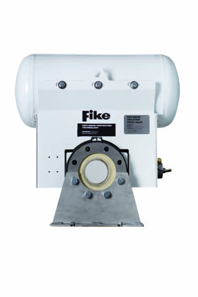
Active isolation devices
Active isolation is triggered by an explosion detection and control system. You get supervision, faster response in many cases, and better control over direction of protection.

Active isolation, what it adds:
- Supervision, alarms, and clearer proof of readiness
- Better fit for complex layouts, multiple vessels, and two-direction risk
- Integration with shutdown, fan control, and process interlocks
Learn about the control layer here: Explosion Detection and Control.
Commissioning and proof, what “done” looks like
Isolation is only real when it is installed correctly, supervised correctly, and can be inspected and reset. This is the part that prevents false confidence.
Commissioning checklist
- Confirm device location matches the design intent, including direction of protection
- Verify access for inspection, hatch removal, and reset, do not accept “we will figure it out later”
- Confirm supervision signals are wired and visible at the controller and at the plant interface if applicable
- Confirm plant air, cartridges, or actuators meet the device requirements, and are monitored where required
- Document final as-built, including line sizes, distances, and setpoints
Maintenance and reset planning
Isolation devices live in dirty, vibrating, high-cycle environments. If your maintenance plan is vague, your protection is vague.
What to plan before you buy
- Inspection access, clearances, and lift points if valves are heavy
- How the device is reset after an activation, who does it, what parts are required
- Spare parts strategy for sleeves, cartridges, gaskets, and sensors
- Shutdown and lockout procedure, including who has authority to return to service
SSI provides design, installation, and service so your isolation protection stays ready, not just installed.
Quote request checklist
If you want fast, accurate quotes and fewer redesign loops, send this information up front.
- Line details: diameter, material, flanges, operating pressure or vacuum, temperature
- Geometry: straight run available, bend locations, branch points, and distances
- Airflow: typical velocity, direction of normal flow, any reverse flow events
- Dust data: Kst, Pmax, MIE if available, or testing status
- Process constraints: sanitation, contamination tolerance, sticky or fibrous dust behavior
- Protection scope: which vessels are protected already, venting or suppression, and which lines remain
Standards and design references
Explosion isolation design is typically validated against recognized standards and authority requirements. The most common reference for explosion prevention systems is NFPA 69. Your insurer and AHJ may have additional requirements.
- NFPA standards portal (look for NFPA 69 and related combustible dust standards)
- OSHA (combustible dust and process safety guidance)
If you need the full system view, start here: Industrial Explosion Protection Systems.
Frequently asked questions
How far from equipment should an isolation valve be installed?
It depends on the device, line size, dust data, and the protected vessel. Many devices have tested minimum and maximum installation distances. Start with the device data sheet and validate against your exact geometry.
Do I need isolation if I already have suppression or venting?
Often, yes, because suppression or venting protects the vessel, isolation protects the connected lines and downstream equipment. That combination is how facilities avoid a multi-vessel event.
When is passive isolation not a good fit?
When airflow conditions are unstable, interconnections are complex, ignition could occur in multiple places, or you need supervised readiness. In those cases, active isolation is usually the safer engineering choice.
Does chemical isolation contaminate product?
Chemical isolation introduces suppressant into the ductwork or line when it activates. If contamination cannot be tolerated, mechanical isolation is often preferred. SSI can help you evaluate the right method for your process constraints.
What is the fastest way to get to a correct design?
Start with combustible dust testing and a Dust Hazard Analysis, then design the full protection strategy, venting or suppression plus isolation plus detection and control if needed. SSI provides end-to-end support, design, install, service.
Downloads
Get a design review
If you want this done correctly and quickly, do not piece it together from generic diagrams. SSI designs and installs explosion isolation systems for interconnected industrial equipment, and supports inspection and service so your protection stays ready.
Call: 1-800-360-0687
Request: Consultation and isolation layout review
Related pages:
Explosion Isolation,
Explosion Detection and Control,
Explosion Suppression,
Dust Hazard Analysis
Suppression Systems Inc., 155 Nestle Way, Suite 104, Breinigsville, PA 18031