
Emergency Power Shutdown Management System (EPSMS) — Code-Compliant Shutdown Without the Accidental Trip Risk
In mission-critical environments — data centers, server rooms, laboratories, MRI suites, broadcast facilities, industrial control rooms — the ability to shut down power instantly during an emergency is a code requirement. But the same hardware that enables instant emergency shutdown can also cause catastrophic, accidental shutdowns when it’s triggered by anything other than a real emergency.
The traditional Emergency Power Off (EPO) button — the unguarded “big red button” near the door — meets the letter of NFPA 70 (NEC) Article 645.10. It also exposes the facility to one of the most expensive, most preventable forms of downtime in the industry.
An Emergency Power Shutdown Management System (EPSMS) solves both problems. It maintains the full, instant emergency shutdown capability the code requires — and it engineers out the accidental activation risk through layered physical, logical, and electrical safeguards.
Suppression Systems, Inc. (SSI) designs and installs EPSMS solutions for facilities across Pennsylvania, New Jersey, Maryland, Virginia, and Delaware. Our NICET-certified engineers integrate every EPSMS with the fire alarm system, the suppression releasing platform, and the building management infrastructure — so emergency shutdown is coordinated, supervised, and code-compliant from the day it’s commissioned.
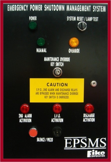
Why the “Big Red Button” Is a Liability
A standard EPO button is a single-pole switch that disconnects everything in the protected space. No confirmation. No time delay. No abort window. No supervised wiring. No logging. It works the same way whether the activation is a fire alarm event, a contractor’s accidental shoulder, or a visitor’s curiosity.
The result is a long list of well-documented accidental activation modes:
- Mistaken identity at the door — visitors and contractors confusing EPO buttons with door release controls
- Physical contact from carts, ladders, racks, tools, or equipment cases passing by
- Wiring faults and supervisory failures that simulate a button press
- Misunderstanding of the button’s scope — pressed to shut down “that server over there”
- Curious visitors during tours, demonstrations, or audits
- Maintenance work near the button — painting, drywall, electrical, cleaning
- Intentional sabotage or disgruntled personnel
The cost when it happens: Total facility outage, hardware damage from ungraceful shutdown, data corruption, extended phased restart sequence, SLA violations, customer impact, and forensic investigation requirements. Read our full guide on accidental EPO activation — causes, real-world impact, and prevention →
What an EPSMS Actually Is
An EPSMS is an intelligent, logic-controlled platform that manages emergency electrical disconnection across the protected space. It replaces the simple relay-driven EPO with a supervised, programmable controller that coordinates the entire shutdown sequence — and that requires deliberate, validated activation before any breaker trips.
A properly engineered EPSMS does three things that a basic EPO cannot:
1. It Confirms Activation Before Tripping
Through two-step activation logic (A/B confirmation), timed press requirements, abort windows, and cross-zoned input validation. No single momentary input — accidental contact, wiring fault, transient voltage — can trip the breakers.
2. It Manages the Complete Shutdown Sequence
Coordinated control of IT equipment power, dedicated HVAC, UPS input, UPS battery disconnect (per UL 1778-2), and any auxiliary systems — in the correct sequence, with the correct timing, and with full logging of every step.
3. It Integrates With Fire Alarm and Suppression
During a confirmed fire or clean agent suppression event, the fire alarm panel commands the EPSMS to execute the shutdown sequence — automatically, in the correct order, with documented event logging. No manual coordination required during the emergency.
What’s Inside an SSI EPSMS Cabinet
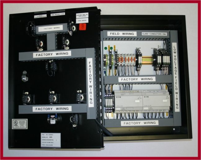
The engineering inside the cabinet is what separates a real EPSMS from a relabeled EPO. SSI’s standard build includes:
- Shunt trip breaker management — remote breaker disconnection via 24VDC or 120VAC control voltage, sized to the facility’s electrical load
- Power-on trip logic — requires positive voltage to initiate shutdown, eliminating false trips from wiring faults, transient power loss, or supervisory failures
- Clearing contacts — protect shunt trip coils from burnout during extended off conditions
- Programmable logic controller — handles activation confirmation, timing, sequencing, and abort logic with configurable parameters per facility
- Supervised control circuits — continuously monitored wiring; any fault, short, or open annunciates as a trouble condition rather than a shutdown
- Optional undervoltage release (UVR) — coordinated with the controller for facilities where the application calls for it
- Event logging and monitoring — real-time breaker status, voltage conditions, activation events, and trip log reporting
- Fire alarm interface — supervised input from the Autocall, Fike, or other UL 864-listed fire alarm panel for coordinated event-based shutdown
Four Layers of Accidental-Activation Protection
Every SSI-designed EPSMS includes coordinated protection at four engineering layers. None is sufficient on its own; together, they make accidental activation effectively impossible.
| Layer | Engineering Detail |
|---|---|
| Physical interface | Recessed mounting, hinged alarmed covers, guarded button rings, differentiated placement from door release controls, clear consequence signage |
| Activation logic | Two-step A/B confirmation, timed press requirement, cross-zoned input validation, programmable abort window with audible warning |
| Wiring topology | Power-on trip logic, supervised circuits with trouble annunciation, isolated control voltage, clearing contacts for shunt coil protection |
| Event accountability | Full event logging — every press, fault, abort, and shutdown timestamped and attributed; supports forensic root cause analysis |
The protections do not slow legitimate emergency response. A deliberate two-step activation adds fractions of a second to an intentional press — well within NFPA 70 and NFPA 75 response timeframes. What it eliminates is the unintentional activation that causes far more outages than actual emergencies do.
The Full Code and Listing Stack
Every EPSMS SSI designs and installs is engineered to meet the complete applicable code and UL listing stack — and documented for AHJ acceptance.
| Standard | What It Governs |
|---|---|
| NFPA 70 Article 645.10 | Disconnecting means for IT equipment in information technology equipment rooms — the primary code basis for EPSMS |
| NFPA 70 Article 645.11 | Uninterruptible power supply requirements within the disconnecting means framework |
| NFPA 75 | Fire Protection for Information Technology Equipment — coordinated shutdown during fire events and clean agent suppression |
| NFPA 72 | Interface and supervision requirements between the fire alarm panel and the EPSMS controller |
| NFPA 2001 | Clean agent suppression coordination — when fire alarm + suppression triggers EPSMS during pre-discharge sequence |
| UL 1778-2 | Uninterruptible power supply battery disconnect requirements — addressed by EPSMS through coordinated battery isolation |
| UL 864 | Fire alarm control unit listing — required for the panel that interfaces with the EPSMS |
SSI handles design submittals, AHJ coordination, acceptance testing documentation, and ongoing annual inspection requirements — so compliance is maintained throughout the system’s operational life, not just at commissioning.
The Integrated Emergency Shutdown Sequence
When EPSMS is properly integrated with the fire alarm and suppression platform, the response to a confirmed fire event in a protected space executes automatically — no manual coordination required during the emergency:
- Cross-zoned fire detection confirms the event at the Fike releasing panel or Autocall fire alarm panel
- Pre-discharge alarm and timed delay activate; audible warning alerts occupants and provides operator abort window
- HVAC shutdown command issued; dampers close to contain suppression agent and prevent fire spread
- Clean agent suppression discharges into the protected space
- Fire alarm panel issues confirmed activation signal to the EPSMS controller
- EPSMS executes the programmed shutdown sequence in the correct order — IT equipment, dedicated HVAC, UPS input, UPS battery
- Shunt trip breakers operate; supervised circuits confirm successful disconnection
- Full event logged across fire alarm, suppression, and EPSMS systems with synchronized timestamps
- Monitoring station notified; first responders dispatched with documented event information
For a complete view of how fire alarm, suppression, and EPSMS integrate, see Fire Alarm and Suppression System Integration — A Practical Guide.
Where SSI Deploys EPSMS
Data centers are the most common application, but EPSMS is the right solution anywhere code-required emergency shutdown must be balanced against the operational cost of accidental activation:
Enterprise and Colocation Data Centers
The primary EPSMS application. NEC Article 645 compliance, coordinated UPS battery disconnect per UL 1778-2, clean agent suppression integration, and protection against the documented downtime risk of accidental EPO presses in high-traffic, multi-personnel facilities.
Server Rooms and IT Closets
Smaller-scale EPSMS deployments for enterprise server rooms, network operations centers, and distributed IT spaces. Coordinated shutdown sequencing protects equipment during clean agent discharge events while preventing nuisance trips during routine maintenance.
MRI Suites and Medical Imaging
MRI rooms have specific quench, magnet shutdown, and equipment power requirements that benefit from coordinated logic-controlled shutdown. Accidental power loss to imaging equipment is both expensive and potentially harmful to ongoing diagnostic procedures.
Broadcast Studios and Network Operations
On-air interruption from an accidental shutdown is catastrophic in broadcast environments. EPSMS provides the required emergency capability while maintaining the operational confidence that air time is protected from inadvertent activation.
Laboratory and Research Facilities
Long-running experiments, sensitive analytical equipment, and high-value research environments where accidental power loss can destroy hours, days, or months of work in a single moment. EPSMS provides the emergency capability without the operational risk.
Industrial Control Rooms and SCADA Facilities
Process control environments where coordinated emergency shutdown must interact with the process safety system, the fire alarm platform, and the operator interface. EPSMS provides the centralized logic for safe, supervised shutdown.
Telecommunications Facilities
Carrier hotels, switching centers, and network nodes where service interruption affects customer infrastructure beyond the facility itself. Coordinated, logged, supervised shutdown supports both compliance and service-level commitments.
The SSI Approach to EPSMS Engineering and Delivery
For over 40 years, SSI has been engineering coordinated fire, suppression, and emergency control systems for the East Coast’s most demanding facilities. Our NICET-certified engineers handle EPSMS as part of an integrated life safety design — not as a standalone electrical project.
1. Site Evaluation and Risk Assessment
Walk-through of existing EPO infrastructure, identification of accidental activation risk factors, review of fire alarm and suppression integration, and code compliance assessment against current NEC and NFPA editions.
2. Engineered Design
Controller selection, breaker coordination, activation logic configuration, fire alarm panel interface, and AHJ submittal documentation. Every design tailored to the specific facility’s electrical layout, load, and operational requirements.
3. Coordinated Installation
Factory-trained technicians install the EPSMS, working alongside the facility’s electrical contractor and IT operations team to stage the cutover and minimize service impact. Existing shunt trip breakers are typically reused; control wiring and the EPSMS controller are new.
4. Commissioning and Acceptance Testing
Full functional testing of activation logic, fire alarm interface, supervisory functions, abort sequences, and breaker operation — with documented results for the AHJ and the facility’s records.
5. Annual Inspection and Service
Annual functional testing per NFPA 70, NFPA 72, and NFPA 75 schedules. Logic verification, supervisory circuit testing, and event log review. The team that installs the system maintains it through its operational life.
Frequently Asked Questions
Is EPSMS required by code, or is a basic EPO button sufficient?
NFPA 70 (NEC) Article 645.10 requires a disconnecting means — it does not specify EPSMS specifically. A basic EPO button can satisfy the code requirement. However, an EPSMS satisfies the same code while engineering out accidental activation risk and adding fire alarm integration, supervised circuits, and event logging that a basic EPO cannot provide. Many AHJs and insurance underwriters now favor or require EPSMS-class implementations for mission-critical facilities.
Can EPSMS be retrofitted into an existing data center?
Yes. EPSMS retrofits are common and can be staged to minimize service disruption. The existing shunt trip breakers are typically reused; the EPO buttons, control wiring, and EPSMS controller are replaced. Fire alarm integration is added or upgraded as part of the project. SSI handles the engineering, AHJ coordination, and staged installation to align with your operational windows.
What is power-on trip logic and why does it matter?
Power-on trip logic means the system requires positive voltage to initiate shutdown. Traditional EPO circuits often use normally-closed contacts, where any break in the control circuit — a wiring fault, corroded contact, or power loss to the EPO relay — appears identical to a button press and trips the breakers. Power-on trip eliminates this category of false activation by requiring an active, validated voltage signal to initiate shutdown.
Will EPSMS slow down legitimate emergency response?
No. Two-step activation, time delays, and abort windows are engineered to add fractions of a second to a deliberate emergency activation — well within NFPA 70 and NFPA 75 response timeframes. The protection is against momentary, accidental, or non-emergency activation, not against genuine emergency response. The EPO still works exactly as intended when actually needed.
How does EPSMS coordinate with a clean agent suppression system?
During a confirmed clean agent discharge event, the releasing panel — typically a Fike Cheetah Xi or SHP-PRO — issues a supervised signal to the EPSMS controller after the pre-discharge sequence completes. EPSMS executes the programmed shutdown in the correct order, ensuring electrical equipment is de-energized in coordination with agent discharge per NFPA 75 requirements. The entire sequence is automatic, logged, and code-compliant.
Does EPSMS handle UPS battery disconnect?
Yes. UL 1778-2 requires that UPS systems include a means to disconnect battery circuits during emergency shutdown — a common gap in older EPO installations that disconnected only AC input. SSI’s EPSMS includes coordinated UPS battery disconnect as part of the standard shutdown sequence, satisfying UL 1778-2 along with NEC Article 645.11 UPS requirements.
Can EPSMS be tested without taking down the facility?
Yes. Functional testing of EPSMS activation logic, fire alarm interface, supervisory circuits, and event logging can be performed without tripping the breakers — through controller test modes and simulated activation procedures. Full breaker operation testing is typically performed during scheduled maintenance windows. SSI’s testing protocols are designed to verify the system without disrupting service.
What happens if the EPSMS itself loses power?
Because SSI’s EPSMS uses power-on trip logic, loss of power to the EPSMS controller does not trip the breakers. The system simply annunciates a trouble condition through the supervisory interface and the fire alarm panel. This is the opposite behavior from traditional EPO circuits, which often trip on power loss — and is one of the primary engineering advantages of EPSMS.
Protect Uptime. Maintain Compliance. Prevent the Accidental Shutdown.
SSI’s Emergency Power Shutdown Management System delivers the engineered, integrated, code-compliant electrical shutdown your facility needs to satisfy NFPA 70 and NFPA 75 — without the operational risk of a basic EPO button. Whether you’re planning a new build, retrofitting an existing data center, or responding to an inspection finding, our certified engineers will deliver a system designed to work exactly when it should — and never when it shouldn’t.
Contact SSI today to schedule an EPSMS consultation or facility assessment with our certified engineers. We serve Pennsylvania, New Jersey, Maryland, Virginia, and Delaware.